UNC threaded insert dimensions — length & hole-size ranges
There is no ANSI or ASME dimensional standard for threaded inserts for plastics — knurl geometry, lengths and hole sizes are manufacturer-specific. What IS broadly consistent across US catalogs is the installed-hole series. The chart below gives the length and starting-hole ranges spanned by two independently verified US catalog series (one straight-knurl press-in line, one tapered heat-set line), 2-56 to 3/8-16 UNC.
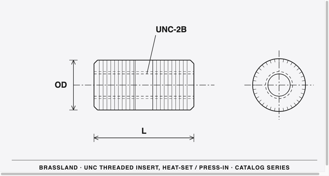
Knurled insert for plastics — OD and length (L); both are vendor-specific, so the chart lists ranges.
Ranges span two independently verified US catalog series (straight-knurl press-in and tapered heat-set, July 2026). Knurl OD and exact lengths are vendor-specific and NOT interchangeable between makes — installed hole size and boss diameter are always per the manufacturer drawing. Test-fit before production.
Because insert geometry is proprietary to each maker, this chart publishes ranges only. Published design guides also recommend a minimum hole depth of insert length plus roughly 0.030 in. and a minimum boss diameter of about twice the knurl OD for heat-set styles.
Why ranges, not single values
The hole-size series is broadly consistent across vendors — a 4-40 insert installs in a ≈ 0.156–0.159 in. hole, an 8-32 in ≈ 0.219–0.234 in., a 1/4-20 in ≈ 0.313–0.315 in. — but knurl geometry, flange diameters and length steps differ from catalog to catalog. A chart that printed one exact number per size would be quietly wrong for every vendor except one. Design against the manufacturer drawing of the insert you will actually buy, or have the insert made to your own drawing.
Boss & hole design rules
Insert body OD and length are vendor-specific, but hole and boss geometry follow well-established design rules from established insert-design references. These apply to both heat-set and press-in inch-series inserts.
Oversize holes cut pull-out and torque; undersize holes crack the boss. Moulded holes out-perform drilled. Full method tables and heat-set tip temperatures: insert installation guide.
Indicative ranges for correctly installed heat-set/ultrasonic inserts in representative engineering thermoplastics — unfilled nylon/ABS/PC and 30% glass-filled nylon. These are a general design guide, not a specification.
Indicative typical performance only — correctly installed heat-set/ultrasonic inserts in representative engineering thermoplastics, as a general design guide. Actual performance depends heavily on your resin and filler, hole and boss geometry, and installation process. Always validate on your own boss, resin and process; contact us for application-specific data. Figures are ranges, not spec numbers. Glass fill does not reliably raise pull-out — it mainly raises torque-out, stiffness and creep resistance. The 1/4-20 glass-filled figures rest on a single source and are supplied on request.
Need these inserts in brass?
More reference charts & tools
Frequently asked questions
Is there a standard for UNC threaded insert dimensions?
No. Threaded inserts for plastics have no ANSI or ASME dimensional standard — each manufacturer defines its own knurl geometry, lengths and recommended holes. The installed-hole series is broadly consistent across makes, but insert bodies are not interchangeable; the controlling document is the manufacturer drawing.
What hole size does a 4-40 heat-set insert need?
Verified catalog series run approximately 0.156 to 0.159 in. starting hole for 4-40, with the exact figure set by the insert style (straight press-in versus tapered heat-set), hole form and boss design — confirm against the manufacturer drawing.
Can I substitute one manufacturer’s insert for another?
Only after qualification. Hole-size recommendations largely agree between catalogs, but knurl outside diameters and lengths differ (a 4-40 knurl OD runs 0.166 in. in one verified series and 0.172 in. in another), which changes retention. Test before production.
What lengths do UNC inserts for plastics come in?
Typical verified catalog ranges run from 0.115–0.188 in. at 2-56 up to 0.375–0.625 in. at 3/8-16, with each thread size spanning the lengths listed in the chart. Exact length steps are vendor-specific.
What is the difference between heat-set and press-in inserts?
Heat-set (or ultrasonic) inserts are tapered and installed with heat or ultrasonic energy that re-melts the plastic into the knurls; press-in inserts have straight knurled bodies pressed cold into a plain hole. The right choice depends on the plastic and the pull-out and torque-out loads.
Last reviewed: July 2026. This chart records verified catalog ranges, not a governing standard — the controlling document for any order is the manufacturer drawing.