Brass Inserts
Brass mould-in threaded inserts — DIN 16903 knurled forms for plastic overmoulding
Standard Parts · DIN 16903 · CW614N Brass

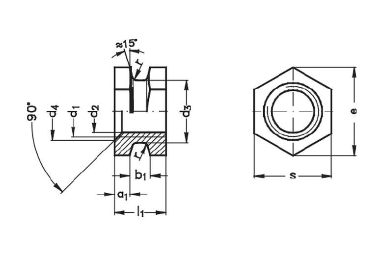
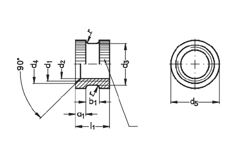
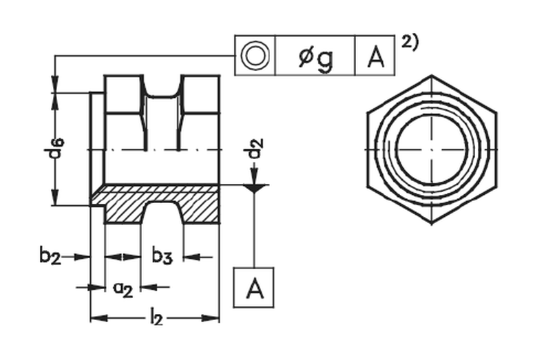
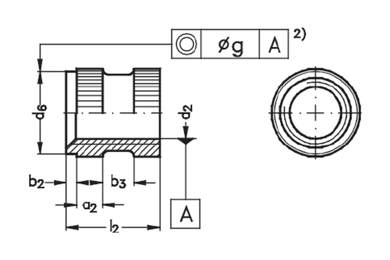
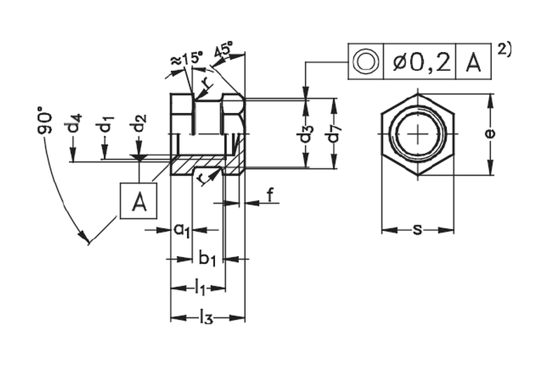
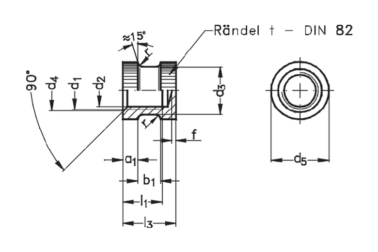
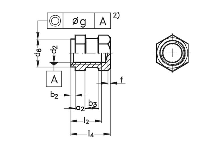
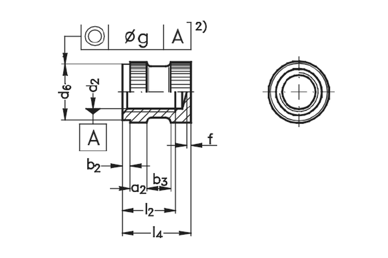
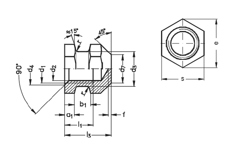
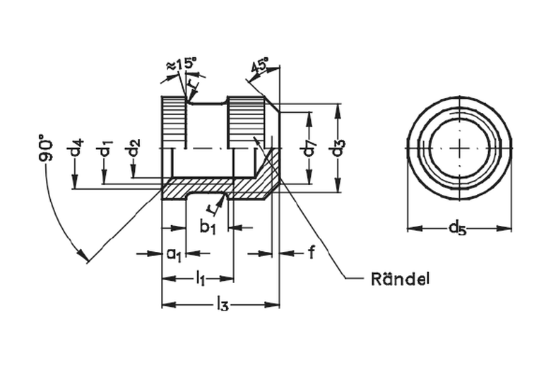
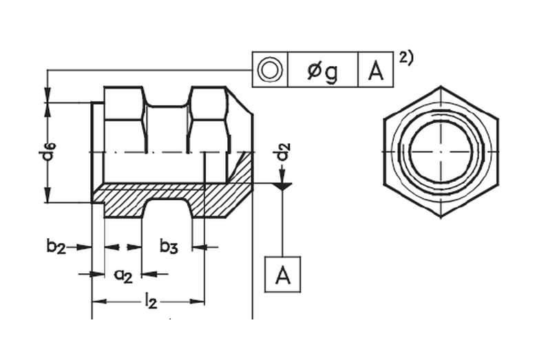
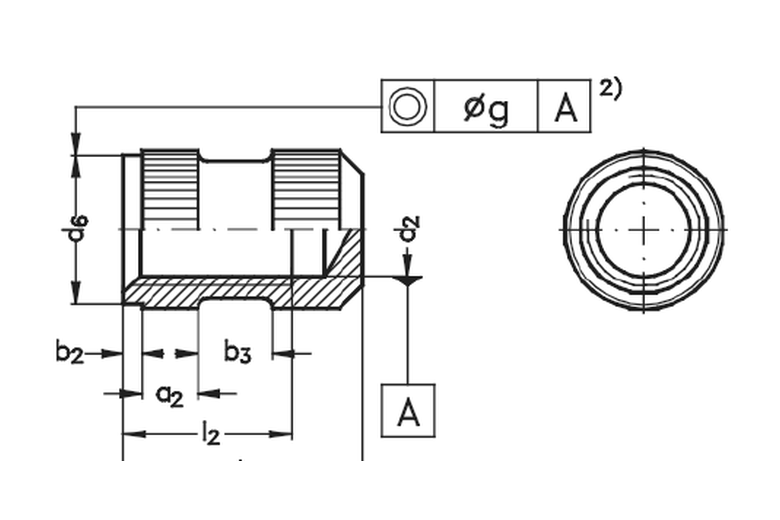
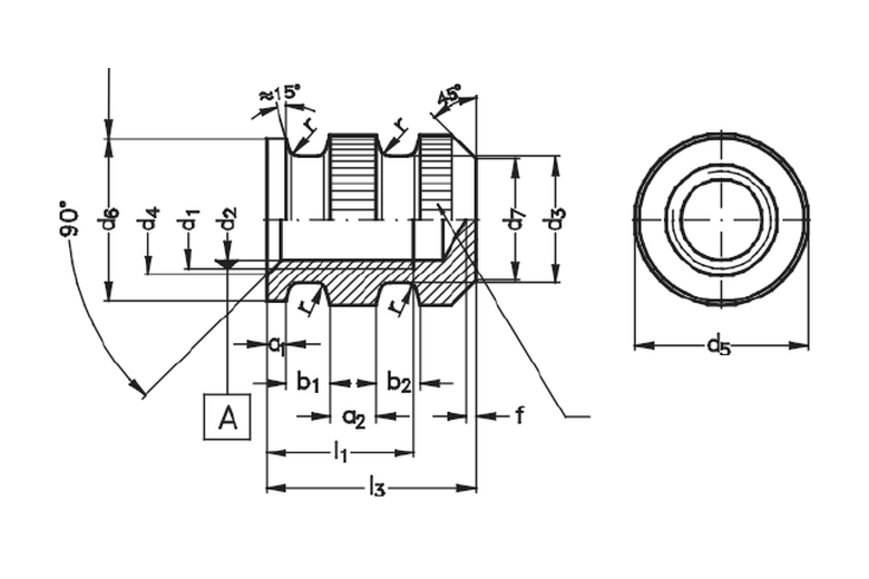
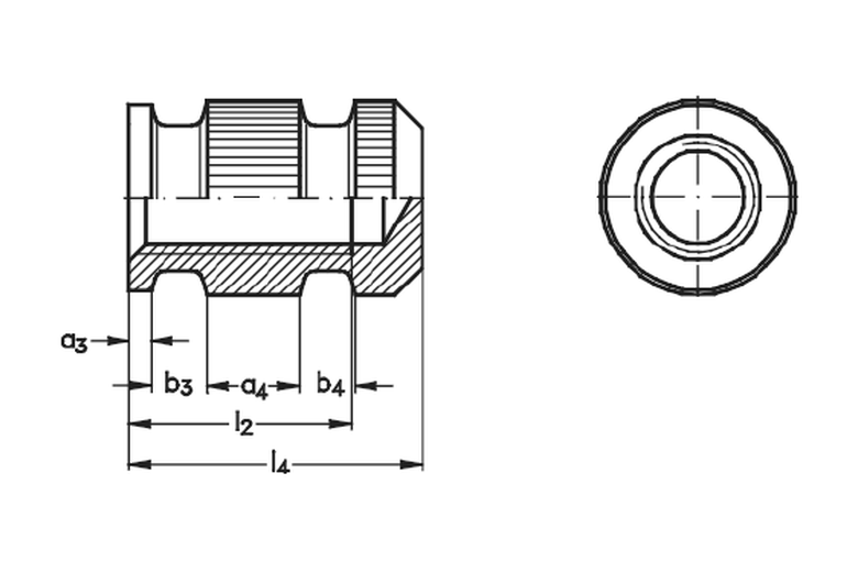
Mould-In Inserts — DIN 16903

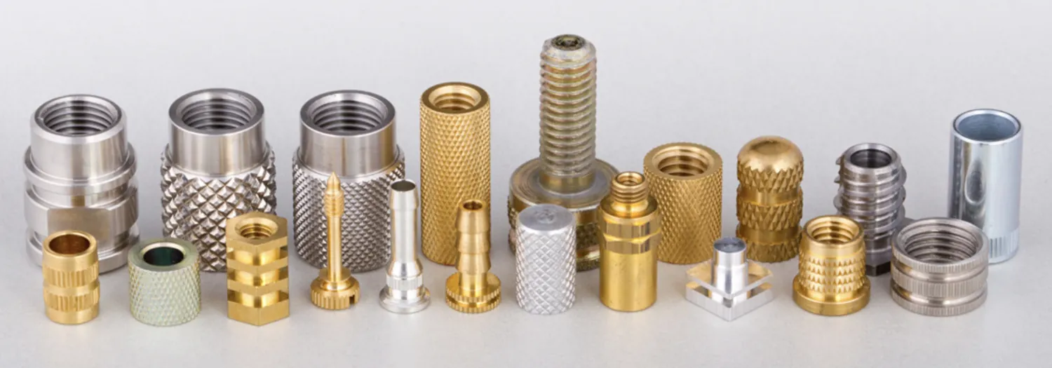
All 14 forms — A, B, C, D, E, F, G, H, P, Q, R, S, T, U. Knurled brass threaded inserts for plastic overmoulding. M2 to M16, ISO metric 6H tolerance. Diamond and straight knurl available. Made to order in Jamnagar — no stock items.
14
Form variants per DIN 16903
A · B · C · D · E · F · G · H · P · Q · R · S · T · U
M2 – M16
ISO metric thread range, 6H tolerance
M2 · M2.5 · M3 · M3.5 · M4 · M5 · M6 · M8 · M10 · M12 · M16
CW614N
CuZn39Pb3 · EN 12164 · RoHS & REACH compliant
Brass only · Made to order
Cast-In Inserts for Epoxy-Resin & Composite Insulators

Beyond thermoplastic over-moulding, these inserts are widely used as cast-in / mould-in inserts encapsulated in epoxy cast-resin and SMC/BMC composite parts — the brass terminals and threaded inserts moulded into HV/MV insulators, bushings, instrument transformers, switch rods and standoff insulators. For these thermoset applications we machine anti-rotation knurling, pull-out grooves and sealed or blind bores that keep resin out of the threads during casting, in CW614N / CW617N brass with tin or nickel plating to spec. Supplied to cast-resin and composite-insulator manufacturers serving energy distribution, rail and industrial equipment. Switchgear components →

Forms A · B · C · D — Basic Knurled Inserts
Brassland brass moulding insert DIN 16903 Form A — hexagonal body, no shoulder (6-kant ohne Ansatz) engineering drawing
A
Hex Body · No Shoulder
Hexagonal OD (6kt) with open through-thread, no locating shoulder. The hex body provides inherent anti-rotation without a machined slot. Compact — body length l₁ ≈ d₁. Thread range M2–M12.
Hexagonal Open thread No shoulder M2 – M12
Brassland brass moulding insert DIN 16903 Form B — round body, no shoulder (rund ohne Ansatz) engineering drawing
B
Round Body · No Shoulder
Round OD with open through-thread, no shoulder. Knurl alone provides pull-out and torque resistance. Most compact and economical form. Body length l₁ ≈ d₁. Thread range M2–M12.
Round Open thread No shoulder M2 – M12
Brassland brass moulding insert DIN 16903 Form C — hexagonal body with locating shoulder (6-kant mit Ansatz) engineering drawing
C
Hex Body · With Shoulder
Hexagonal OD with a locating shoulder (Ansatz) at the insertion end. The shoulder sets insert depth and prevents sinking during overmoulding. Body length l₂ ≈ 1.5 × d₁. Thread range M2–M12.
Hexagonal Open thread With shoulder M2 – M12
Brassland brass moulding insert DIN 16903 Form D — round body with locating shoulder (rund mit Ansatz) engineering drawing
D
Round Body · With Shoulder
Round OD with locating shoulder — the most widely specified DIN 16903 form. Combines knurl retention with precise depth control. Body length l₂ ≈ 1.5 × d₁. Order ref: DIN 16903 Messing D–M4. Thread range M2–M12.
Round Open thread With shoulder M2 – M12
Dimensions — Forms A, B, C, D (mm)
d₁ = nominal thread (6H) · d₂ = pre-mould bore Ø H11 · d₃ = body OD h12 · d₆ = knurl OD h11 · l₁ = body length A/B · l₂ = body length C/D (≈1.5×d₁) · a₁ = knurl pitch · b₁ = knurl height · s = hex AF (A & C only) · (—) not applicable
Thread d₁d₂ H11
pre-bore
d₃ h12
body OD
d₆ h11
knurl OD
l₁ h12
A / B
l₂ h12
C / D
a₁
knurl pitch
b₁
knurl ht
s
hex AF
e
hex diag
M21.603.23.52.33.50.80.8
M2.52.053.43.82.64.00.90.8
M32.503.84.23.04.50.91.25.05.8
(M3.5)2.904.55.03.55.51.01.45.56.35
M43.305.05.54.06.01.21.46.06.9
M54.206.47.05.07.51.61.87.08.1
M65.007.48.06.09.01.82.49.010.4
M86.8010.410.08.012.02.04.011.012.7
M108.5013.012.510.015.03.04.014.016.2
M1210.3017.016.012.018.03.55.019.021.9
Forms E · F · G · H — With Bottom Collar (STn26)
Brassland brass moulding insert DIN 16903 Form E — hexagonal body with bottom collar, no top shoulder engineering drawing
E
Hex Body · Collar · No Top Shoulder
Hexagonal OD with machined collar (depth f) at the insertion end, no top shoulder. Plastic wraps the collar during moulding — greatly increases axial pull-out resistance. Lengths l₁ (body) and l₃ (total). Thread range M2–M12.
Hexagonal Bottom collar No top shoulder M2 – M12
Brassland brass moulding insert DIN 16903 Form F — round body with bottom collar, no top shoulder engineering drawing
F
Round Body · Collar · No Top Shoulder
Round OD with bottom collar (depth f), no top shoulder. Common for PCB housings and electronics enclosures where high pull-out is needed but depth is controlled by tooling. Lengths l₁ and l₃. Thread range M2–M12.
Round Bottom collar No top shoulder M2 – M12
Brassland brass moulding insert DIN 16903 Form G — hexagonal body with bottom collar and top locating shoulder engineering drawing
G
Hex Body · Collar + Top Shoulder
Hexagonal OD with bottom collar AND top locating shoulder. Maximum retention — hex anti-rotation, collar for pull-out, shoulder for precise depth. Lengths l₂ (body) and l₄ (total). Thread range M2–M12.
Hexagonal Bottom collar Top shoulder M2 – M12
Brassland brass moulding insert DIN 16903 Form H — round body with bottom collar and top locating shoulder engineering drawing
H
Round Body · Collar + Top Shoulder
Round OD with bottom collar AND top locating shoulder. For applications where both precise depth setting and high axial pull-out resistance are critical. Lengths l₂ and l₄. Thread range M2–M12.
Round Bottom collar Top shoulder M2 – M12
Dimensions — Forms E, F, G, H (mm)
f (+0.2) = collar depth · d₇ = collar bore Ø · l₁/l₃ = lengths for E & F (no top shoulder) · l₂/l₄ = lengths for G & H (with top shoulder) · s = hex AF (E & G only) · (—) not applicable
Thread d₁d₂ H11
pre-bore
d₃ h12
body OD
d₆ h11
knurl OD
d₇
collar Ø
f +0.2
collar depth
l₁ h14
E/F body
l₂ h14
G/H body
l₃ h12
E/F total
l₄ h12
G/H total
s
hex AF
M21.603.23.50.322.33.53.14.3
M2.52.053.43.80.322.64.03.44.8
M32.503.84.24.20.323.04.53.85.35.0
(M3.5)2.904.55.05.50.503.55.54.56.55.5
M43.305.05.56.00.504.06.05.07.06.0
M54.206.47.07.00.505.07.56.08.57.0
M65.007.48.09.00.506.09.07.010.09.0
M86.8010.410.011.00.808.012.09.513.511.0
M108.5013.012.514.00.8010.015.011.516.514.0
M1210.3017.016.019.00.8011.017.013.519.519.0
Forms P · Q · R · S — With Anti-Rotation Slot
Brassland brass moulding insert DIN 16903 Form P — hexagonal body with anti-rotation slot, no shoulder engineering drawing
P
Hex Body · Slot · No Top Shoulder
Hexagonal OD with machined longitudinal slot (depth f). Plastic fills the slot during moulding and locks the insert against rotation. Hex body plus slot gives dual anti-rotation. Lengths l₁ (body) and l₃ (total). Thread range M2–M12.
Hexagonal Anti-rotation slot No top shoulder M2 – M12
Brassland brass moulding insert DIN 16903 Form Q — round body with anti-rotation slot, no shoulder engineering drawing
Q
Round Body · Slot · No Top Shoulder
Round OD with longitudinal anti-rotation slot. The most widely specified slot form — knurl and slot together lock against rotation and pull-out. Lengths l₁ and l₃. Specified for high-cycle assemblies. Thread range M2–M12.
Round Anti-rotation slot No top shoulder M2 – M12
Brassland brass moulding insert DIN 16903 Form R — hexagonal body with anti-rotation slot and top locating shoulder engineering drawing
R
Hex Body · Slot + Top Shoulder
Hexagonal OD with anti-rotation slot AND top locating shoulder. Hex + slot + shoulder — maximum anti-rotation and precise depth control in one insert. Lengths l₂ and l₄. Thread range M2–M12.
Hexagonal Anti-rotation slot Top shoulder M2 – M12
Brassland brass moulding insert DIN 16903 Form S — round body with anti-rotation slot and top shoulder engineering drawing
S
Round Body · Slot + Top Shoulder
Round OD with anti-rotation slot AND top locating shoulder. For high-cycle applications where both rotation lock and controlled insert depth are critical. Lengths l₂ and l₄. Thread range M2–M12.
Round Anti-rotation slot Top shoulder M2 – M12
Dimensions — Forms P, Q, R, S (mm)
f (+0.2) = slot depth · d₇ = slot bore Ø · l₁/l₃ = lengths for P & Q (no top shoulder) · l₂/l₄ = lengths for R & S (with top shoulder) · s = hex AF (P & R only) · (—) not applicable
Thread d₁d₂ H11
pre-bore
d₃ h12
body OD
d₆ h11
knurl OD
d₇
slot bore
f +0.2
slot depth
l₁ h14
P/Q body
l₂ h14
R/S body
l₃ h12
P/Q total
l₄ h12
R/S total
s
hex AF
M21.603.23.52.50.42.33.54.05.2
M2.52.053.43.82.50.42.64.04.66.0
M32.503.84.22.80.53.04.55.57.05.0
(M3.5)2.904.55.03.50.53.55.56.08.05.5
M43.305.05.54.00.54.06.07.09.06.0
M54.206.47.05.00.55.07.58.310.87.0
M65.007.48.06.00.56.09.09.812.89.0
M86.8010.410.07.00.88.012.012.616.611.0
M108.5013.012.510.00.810.015.015.020.014.0
M1210.3017.016.012.01.012.018.017.823.819.0
Forms T · U — Closed, Heavy Construction · DIN 16903 (1991)
Brassland brass moulding insert DIN 16903 Form T — closed heavy construction, shorter body M2 to M6 engineering drawing
T
Closed · Heavy · Shorter Body (M2–M6)
Closed end (blind bore) — no fluid or debris penetration. Larger body OD than basic forms for the same thread. Wide base flange distributes load across a wider area in thin-wall mouldings. Lengths l₁ (body) and l₃ (total). Thread range M2–M6 only.
Round Closed / blind Heavy construction M2 – M6
Brassland brass moulding insert DIN 16903 Form U — closed heavy construction, extended body M4 to M16 engineering drawing
U
Closed · Heavy · Extended Body (M4–M16)
Closed end with longer body — extends the heavy-duty range from M4 to M16. For die-cast zinc and aluminium parts and thick-section thermoplastics. Lengths l₂ (body) and l₄ (total). Order ref: DIN 16903 Messing U–M4. Thread range M4–M16.
Round Closed / blind Heavy construction M4 – M16
Dimensions — Forms T, U (mm) · Thread extends to M16
d₆ h11 = knurl OD · d₇ = base bore Ø · f (+0.2) = base collar depth · l₁/l₃ = Form T · l₂/l₄ = Form U · (—) not available for that size/form
Thread d₁d₂ H11
pre-bore
d₃ h12
body OD
d₆ h11
knurl OD
d₇
base bore
f +0.2
base collar
l₁ h14
Form T
l₂ h14
Form U
l₃ h12
T total
l₄ h12
U total
M21.603.24.53.40.43.55.2
M2.52.053.55.03.60.44.06.0
M32.504.05.53.80.54.57.0
(M3.5)2.904.66.04.50.55.58.0
M43.305.37.05.00.56.08.09.011.0
M54.206.69.06.00.57.510.010.513.3
M65.007.810.07.00.59.012.012.815.8
M86.8010.512.09.00.816.020.6
M108.5013.015.012.00.820.025.0
M1210.3015.718.015.01.024.029.8
M1614.1021.024.019.01.232.039.5
Material · Knurl · Ordering
Material — Brass Only
CW614N (CuZn39Pb3)
All Brassland moulding inserts are machined from CW614N (CuZn39Pb3) free-machining brass rod to EN 12164 as standard — the very alloy the DIN 16903 standard references. Its lead phase (2.5–3.5% Pb) breaks chips cleanly during turning, knurling and threading, giving consistent surface finish and precise thread geometry across the full M2–M16 range, and it complies with RoHS (lead-in-brass exemption 6c). The same inserts can be quoted in CW617N (CuZn40Pb2) or in lead-free CW724R silicon brass / CW510L for low-lead programmes. Brass only — no steel or stainless variants are offered.
Alloy
CW614N · CuZn39Pb3
Standard
EN 12164 (rod)
Lead content
1.6 – 2.5 % Pb
Tensile strength
380 – 490 MPa
Hardness
75 – 120 HB
Compliance
RoHS (exemption 6c)
CW614N · CuZn39Pb3 RoHS compliant REACH compliant Non-magnetic
Made to Order · Jamnagar
Every insert machined to your specification
Brassland does not hold stock. All DIN 16903 moulding inserts are turned and knurled to order from CW614N bar in our Jamnagar facility. Specify the form letter, thread size, knurl pattern and quantity — we confirm pricing and lead time within one business day.
Diamond knurl — Rändel KR
Cross-hatched pattern. Highest pull-out and torque resistance. Recommended for ABS, PC, PA66 and glass-filled thermoplastics.
Straight knurl — Rändel RGE
Parallel axial ridges. Good pull-out strength, lower torque resistance. For PP, HDPE and softer thermoplastics.
Order reference format
Gewindebuchse DIN 16903 Messing D–M4
→ DIN 16903 · Form D · Brass · M4 thread
Frequently Asked Questions
What are DIN 16903 moulding inserts?

DIN 16903 is the German standard for open-type brass inserts designed to be placed in the mould tool and over-moulded during injection moulding. The plastic flows around the knurls and undercuts as it solidifies, giving the highest pull-out and torque retention of any insert type. Brassland manufactures all 14 standard forms — A, B, C, D, E, F, G, H, P, Q, R, S, T and U.

Which form should I choose — with or without head, with or without through-hole?

Headed forms resist push-through where the screw clamps from the opposite side; unheaded forms suit blind bosses. Through-hole versions let the screw pass completely; closed (blind) versions seal the thread from resin ingress during moulding. The DIN 16903 form letter defines the combination — send your boss design and we’ll confirm the right form.

What sizes and material do you cover?

Standard coverage runs M2 to M16 ISO metric and #4-40 to ½-13 UNC. Inserts are machined from CW614N (CuZn39Pb3) brass per EN 12164, RoHS and REACH compliant, with diamond or straight knurls to DIN 82.

Do moulding inserts work in both thermoplastics and thermosets?

Yes — because the insert is over-moulded rather than installed afterwards, DIN 16903 inserts work in any moulding compound, including glass-filled thermoplastics and thermosets that are too hard for heat-set or self-tapping installation. All production is made to order and confirmed within one business day.

Made to Order · Brassland Jamnagar
Ready to specify?
Send the DIN 16903 form letter, thread size, knurl type and quantity. All inserts machined fresh to your order — confirmed within one business day, supplied to 40+ countries.
← Previous
Self-Tapping & Press-In Inserts
Cold installation — incl. foam-grade types
Next →
The Full Insert Range
Every series and size, in one catalogue
Standards & Compliance References

Specifications this product line is built to

Brassland manufactures to the published EN, ISO and ASTM specifications below. Mill certificates per EN 10204 Type 3.1 are supplied as standard; Type 3.2 (third-party witnessed) available on request. Open any link to verify the standard directly with the publishing body.

EN 12164 / 12165 / 12167
CEN — CW614N brass rod for machining (EN 12164)
DIN 16903
Open-type insert nuts for plastics mouldings — all 14 forms (A–U)
DIN 82
Knurl forms — diamond (RGE) and straight (RAA)
ISO 261 / 965 — Metric Threads
Thread profile & 6H tolerance class for insert internal threads
EN 10204 — Type 3.1
Inspection certificate supplied with every production lot
EU RoHS 2 — 2011/65/EU
Annex III Ex 6(c) valid to 30 Jun 2027
ECHA REACH SVHC
Article 33 disclosure documentation supplied
ISO 9001 · 14001 · 45001
Quality, environment & safety — Brassland certified
Brassland — CW614N Datasheet
CuZn39Pb3 — the alloy every mould-in insert is machined from
Brassland — Standards Guide
Plain-English RoHS, REACH, DZR explainer
Brassland — Certifications
ISO 9001, RoHS, REACH compliance documents
Brassland — Compliance Hub
CMRT, CA Prop 65, SVHC declarations

Last reviewed: June 2026. All Brassland products are made to order — please confirm grade, surface finish, plating and packaging requirements at quotation stage. Standards listed above are referenced; production lots are released against the EN 10204 Type 3.1 inspection certificate accompanying each shipment.

Industries that use moulding inserts
Automotive Electronics & PCB EV Charging Electrical & Switchgear
Related standard parts
Brass Threaded Inserts Special Inserts PCB Press-Fit Terminals
← Back to Standard Parts Catalogue · All Products · Request a Quote →