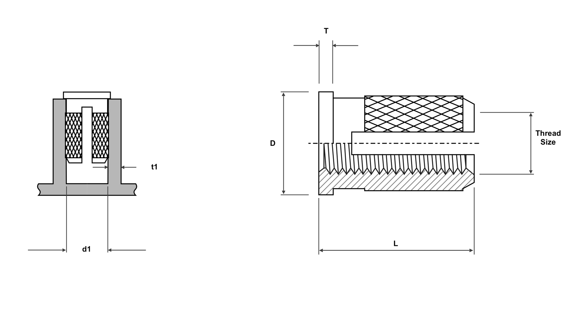
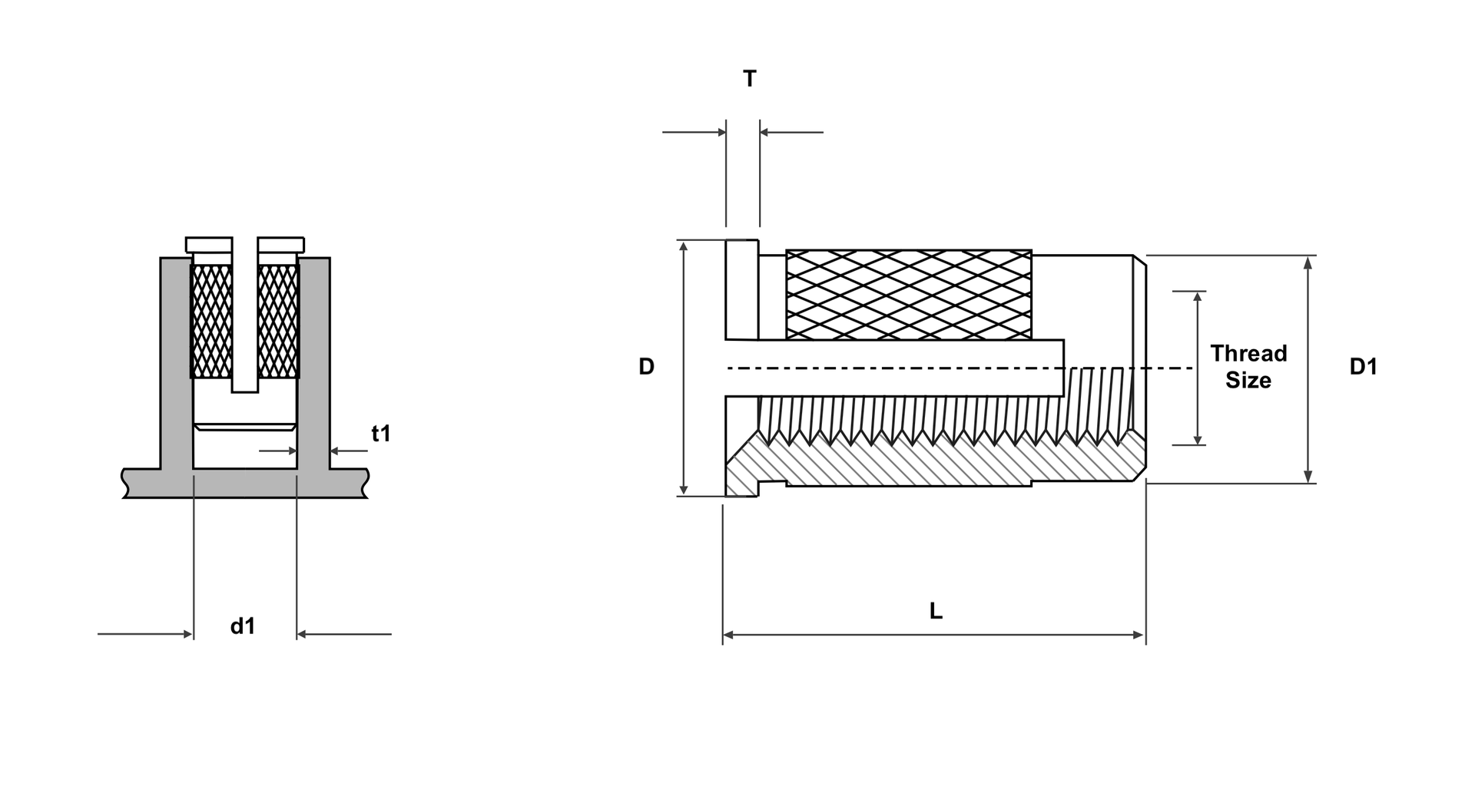
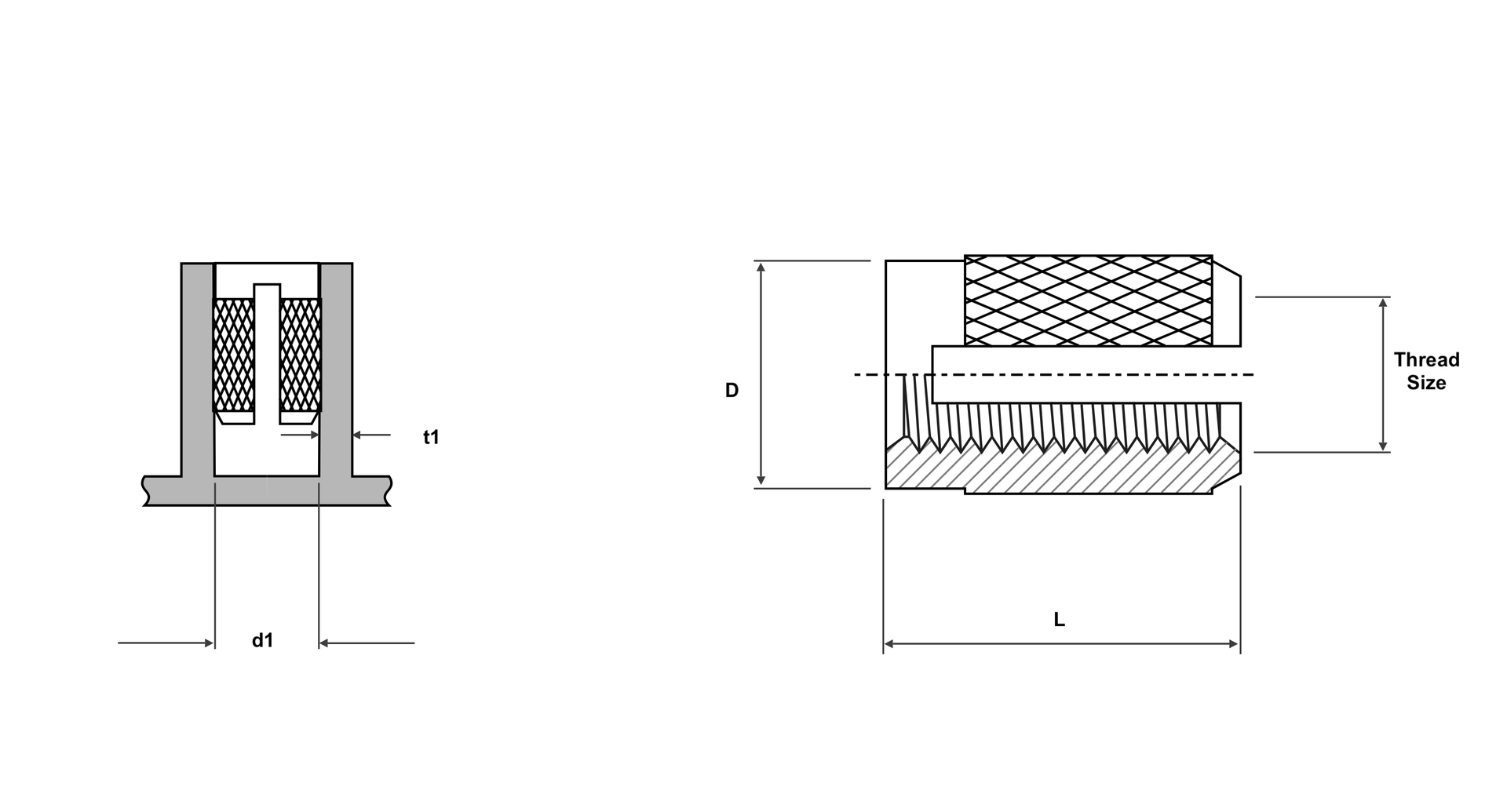
| Thread | D | T | L | d₁ | t₁ |
|---|---|---|---|---|---|
| M2 | 4.8 | 0.43 | 3.9 | 3.2–3.3 | 2.4 min |
| M2.5 | 5.5 | 0.51 | 4.7 | 4.0–4.1 | 3.2 min |
| M3 | 5.5 | 0.51 | 4.7 | 4.0–4.1 | 3.2 min |
| M3.5 | 6.4 | 0.66 | 6.3 | 4.8–4.9 | 3.6 min |
| M4 | 7.1 | 0.82 | 7.9 | 5.6–5.7 | 4.0 min |
| M5 | 7.9 | 1.00 | 9.4 | 6.4–6.5 | 4.8 min |
| M6 | 9.5 | 1.25 | 12.6 | 8.0–8.1 | 6.0 min |
| M8 | 11.1 | 1.25 | 12.6 | 9.6–9.7 | 7.0 min |
| Thread | D | T | L | D₁ | d₁ | t₁ |
|---|---|---|---|---|---|---|
| M2 | 4.8 | 0.43 | 3.9 | 3.2 | 3.2–3.3 | 2.4 min |
| M2.5 | 5.5 | 0.51 | 4.7 | 4.0 | 4.0–4.1 | 3.2 min |
| M3 | 5.5 | 0.51 | 4.7 | 4.0 | 4.0–4.1 | 3.2 min |
| M3.5 | 6.4 | 0.66 | 6.3 | 4.7 | 4.8–4.9 | 3.6 min |
| M4 | 7.1 | 0.82 | 7.9 | 5.5 | 5.6–5.7 | 4.0 min |
| M5 | 7.9 | 1.00 | 9.4 | 6.3 | 6.4–6.5 | 4.8 min |
| M6 | 9.5 | 1.25 | 12.6 | 7.9 | 8.0–8.1 | 6.0 min |
| M8 | 11.1 | 1.25 | 12.6 | 9.5 | 9.6–9.7 | 7.0 min |
| Thread | D | L | d₁ | t₁ |
|---|---|---|---|---|
| M2 | 3.2 | 3.9 | 3.2–3.3 | 2.4 min |
| M2.5 | 4.0 | 4.7 | 4.0–4.1 | 3.2 min |
| M3 | 4.0 | 4.7 | 4.0–4.1 | 3.2 min |
| M3.5 | 4.7 | 6.3 | 4.8–4.9 | 3.6 min |
| M4 | 5.5 | 7.9 | 5.6–5.7 | 4.0 min |
| M5 | 6.3 | 9.4 | 6.4–6.5 | 4.8 min |
| M6 | 7.9 | 12.6 | 8.0–8.1 | 6.0 min |
| M8 | 9.5 | 12.6 | 9.6–9.7 | 7.0 min |
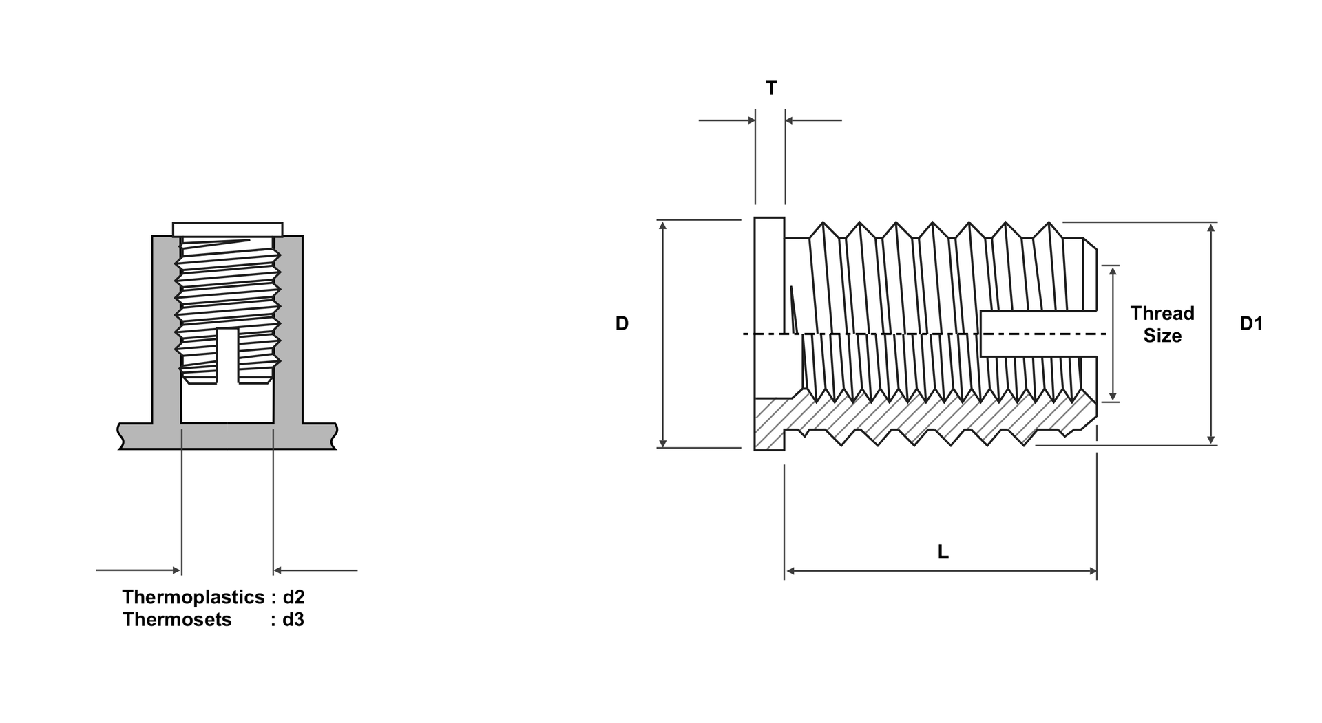
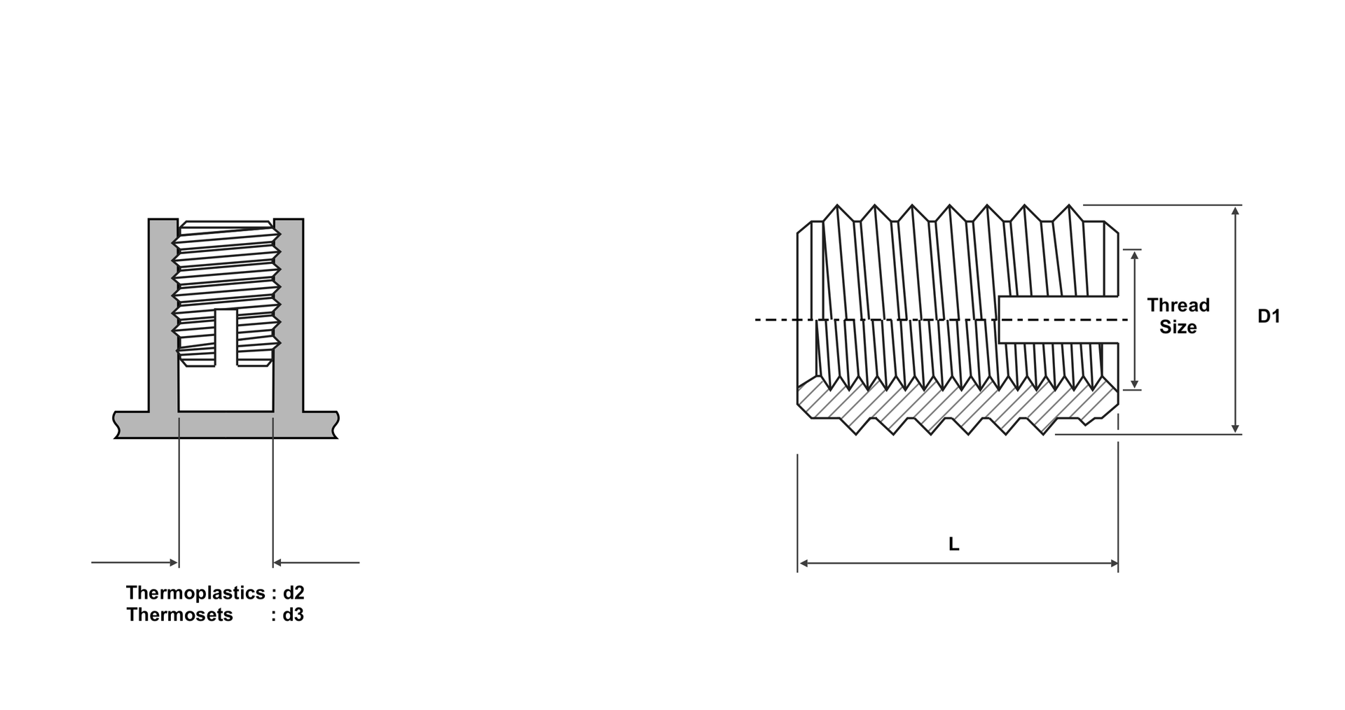
| Thread | D | T | L | D₁ | d₂ | d₃ |
|---|---|---|---|---|---|---|
| M2.5 | 6.0 | 0.58 | 6 | 4.5 | 4.0–4.1 | 4.1–4.4 |
| M3 | 6.5 | 0.58 | 6 | 5.0 | 4.5–4.6 | 4.6–4.8 |
| M3.5 | 7.5 | 0.75 | 8 | 6.0 | 5.3–5.4 | 5.5–5.7 |
| M4 | 8.0 | 0.90 | 8 | 6.5 | 5.8–5.9 | 6.0–6.2 |
| M5 | 9.5 | 1.05 | 10 | 8.0 | 7.1–7.2 | 7.3–7.6 |
| M6 | 12.0 | 1.32 | 14 | 10.0 | 8.6–8.8 | 9.0–9.4 |
| M8 | 14.0 | 1.32 | 15 | 12.0 | 10.6–10.8 | 11.0–11.4 |
| M10 | 16.0 | 1.60 | 18 | 14.0 | 12.6–12.8 | 13.0–13.4 |
| Thread | D₁ | L | d₂ | d₃ |
|---|---|---|---|---|
| M2.5 | 4.5 | 6 | 4.0–4.1 | 4.1–4.4 |
| M3 | 5.0 | 6 | 4.5–4.6 | 4.6–4.8 |
| M3.5 | 6.0 | 8 | 5.3–5.4 | 5.5–5.7 |
| M4 | 6.5 | 8 | 5.8–5.9 | 6.0–6.2 |
| M5 | 8.0 | 10 | 7.1–7.2 | 7.3–7.6 |
| M6 | 10.0 | 14 | 8.6–8.8 | 9.0–9.4 |
| M8 | 12.0 | 15 | 10.6–10.8 | 11.0–11.4 |
| M10 | 14.0 | 18 | 12.6–12.8 | 13.0–13.4 |
Recommended boss-hole diameters and depth for post-mould installation, drawn from established insert-design references. Insert body OD and length are made to your drawing — there is no ISO/DIN dimensional standard for heat-set, press-in or self-tapping insert bodies (only the internal thread is standardised), so we build to your print or our tri-lobe series. Hole and boss geometry, however, follow well-established design rules — published here.
| Thread | Hole Ø heat-set | Hole Ø press-in | Min. hole depth | Boss OD rule | Body OD |
|---|---|---|---|---|---|
| M2 | 3.2 mm | 3.2 mm | L + 2 pitches | 2–3× insert Ø | to drawing |
| M3 | 4.0 mm | 3.95 mm | L + 2 pitches | 2–3× insert Ø | to drawing |
| M3.5 | 4.8 mm | 4.7 mm | L + 2 pitches | 2–3× insert Ø | to drawing |
| M4 | 5.6 mm | 5.55 mm | L + 2 pitches | 2–3× insert Ø | to drawing |
| M5 | 6.4 mm | 6.35 mm | L + 2 pitches | 2–3× insert Ø | to drawing |
| M6 | 8.0 mm | 7.9 mm | L + 2 pitches | 2–3× insert Ø | to drawing |
| M8 | 9.6 mm | 9.5 mm | L + 2 pitches | 2–3× insert Ø | to drawing |
| M10 | on request | on request | L + 2 pitches | 2–3× insert Ø | to drawing |
| Thread | Hole Ø heat-set | Hole Ø press-in | Min. hole depth | Boss OD rule |
|---|---|---|---|---|
| #2-56 | 0.126–0.127″ | 0.124″ | L + 2 pitches | 2–3× insert Ø |
| #4-40 | 0.157–0.158″ | 0.155″ | L + 2 pitches | 2–3× insert Ø |
| #6-32 | 0.188–0.189″ | 0.186″ | L + 2 pitches | 2–3× insert Ø |
| #8-32 | 0.221–0.223″ | 0.217″ | L + 2 pitches | 2–3× insert Ø |
| #10-24/32 | 0.252–0.253″ | 0.249″ | L + 2 pitches | 2–3× insert Ø |
| 1/4-20 | 0.315″ | 0.311″ | L + 2 pitches | 2–3× insert Ø |
| 5/16-18 | 0.377″ | 0.374″ | L + 2 pitches | 2–3× insert Ø |
| 3/8-16 | on request | on request | L + 2 pitches | 2–3× insert Ø |
Heat-set/ultrasonic hole Ø is the convergent value across established insert-design references (M2–M6 agree within ~0.05 mm); M8 and press-in small sizes are single-reference. Body OD and length are proprietary/made-to-drawing — no industry dimensional standard exists. For filled resins, open the hole (see design rules below). M10 and 3/8-16 holes, and press-in force, are provided on request against your resin and boss.
| Boss outer Ø | 2–3× insert Ø (≈2–2.5× hole Ø); the multiplier shrinks as the insert grows |
| Boss min. wall | 50–100% of insert Ø around the insert; min boss OD = insert OD + 2× wall |
| Hole depth | Insert length + 2 thread pitches (heat-set, press-in, mould-in); ≥1.2× length for self-tapping |
| Flush install | Top flush to the surface, max +0.13 mm (0.005″) proud; never sub-flush (jack-out risk) |
| Lead-in taper | Straight hole ≤1° included; tapered hole 8° included (with a tapered insert only) |
| Filler ≥ 15% | Increase the hole Ø by 0.08 mm (0.003″) |
| Filler ≥ 35% | Increase the hole Ø by 0.15 mm (0.006″); interpolate between |
| Headed counterbore | Ø = head Ø + 0.5–1.3 mm (0.02–0.05″), depth = head thickness |
| Moulded vs drilled | Moulded holes out-perform drilled (denser skin); through-hole part thickness > insert length |
| Thermosets | Cannot be heat-set — use mould-in, press-in or self-tapping |
Oversize holes cut pull-out and torque; undersize holes crack the boss. As much as ~75% of an insert’s achievable performance comes down to how well it is installed.
| Resin | Melt / processing (unfilled) | Unfilled tip rule | Filled tip rule |
|---|---|---|---|
| PA6 | melt ~215–225 °C; proc. ~240–280 °C | softening + 28 °C | softening + 83 °C |
| PA66 | melt ~255–265 °C; proc. ~270–300 °C | ||
| ABS | ~200–250 °C processing | ||
| PC | ~280–320 °C | ||
| PP | melt ~160–170 °C; proc. to ~200–250 °C | ||
| POM | ~163 °C (copolymer) to ~205–225 °C (homopolymer) |
| Thread | Unfilled (N) | 30% GF nylon (N) |
|---|---|---|
| M2 | 250–1,150 | 400–900 |
| M3 | 350–2,900 | 1,300–2,300 |
| M4 | 900–4,000 | 1,600–3,900 |
| M5 | 1,200–6,800 | 3,800–7,000 |
| M6 | 1,700–9,200 | 4,300–8,400 |
| M8 | 3,300–13,900 | 6,700–11,800 |
| Thread | Unfilled (Nm) | 30% GF nylon (Nm) |
|---|---|---|
| M2 | 0.3–1.2 | ~0.9 |
| M3 | 0.5–5 | 3.5–4 |
| M4 | 2–10 | 7–7.5 |
| M5 | 5–16 | 13–20 |
| M6 | 7–26 | 15–25 |
| M8 | 18–39 | 34–48 |
Indicative typical performance only — drawn from correctly installed heat-set/ultrasonic inserts in representative engineering thermoplastics, as a general design guide. Actual performance depends heavily on your resin and filler, hole and boss geometry, and installation process. Always validate on your own boss, resin and process; contact us for application-specific data. Values are ranges, not spec numbers. Note: glass fill does not reliably raise heat-set pull-out — it mainly raises torque-out, stiffness and creep resistance. Imperial pull-out/torque-out and the 1/4-20 glass-filled figures are on the imperial reference chart / on request. Mould-in inserts behave differently — see DIN 16903.
Brassland has machined precision brass components in Jamnagar, Gujarat since 2000. The inserts on this page are bar-turned in-house on our own CNC fleet, released against a documented inspection package, and shipped to customers in more than 40 countries. Everything a procurement engineer normally has to ask before raising an RFQ is set out below — capability, order sizes, lead time, paperwork and shipping terms.
| Minimum order | No strict MOQ. First orders typically from ~1,000 pieces per size and type; high-volume OEM call-offs supported. |
| Samples | Prototypes and evaluation samples produced ahead of the production run, on the same process as series parts. |
| Lead time | 3–5 weeks from approved drawing; samples sooner. Blanket orders ship to your agreed call-off dates. |
| Quotation | Typically within 24 hours of receiving a drawing, sample or competitor part number. |
| Documentation | EN 10204 Type 3.1 mill certificate (3.2 on request), Certificate of Conformity, dimensional inspection report. |
| Certification | ISO 9001:2015 · ISO 14001:2015 · ISO 45001:2018, certified by DQS. RoHS and REACH compliant; SVHC disclosure on request. |
| Incoterms 2020 | DDP, FOB or CIF as standard; EXW and DAP on request. |
| Ports of loading | Mundra, Pipavav, Kandla and Nhava Sheva. |
| HS codes | 7415, 7412 and 7419 — the applicable code is confirmed per part at quotation. |
| Export status | Star Export House (Government of India), supplying 40+ countries from Jamnagar, Gujarat, India. |
| Scope of supply | Machined components to your drawing or our insert range — we do not supply finished assemblies. |
There is no strict minimum order quantity. First orders typically start from around 1,000 pieces per thread size and type, which keeps setup economical on both sides, while repeat and OEM schedules run in far higher volumes on the same tooling. Send the annual quantity as well as the first call-off and we will price both.
Quotations are normally issued within 24 hours of receiving a drawing, sample or competitor part number. Series lead time is 3–5 weeks from an approved drawing; prototypes and evaluation samples are made sooner. Scheduled call-offs against a blanket order ship to your agreed dates.
Yes. Insert body diameter, length, knurl form and head geometry are made to your print — only the internal thread is standardised, so the body has no industry dimensional standard. Send a drawing, a 3D model, a sample or a competitor part number and we will confirm the equivalent, the alloy and any plating before tooling. Parts outside the insert range are quoted the same way as made-to-drawing components.
Each shipment carries an EN 10204 Type 3.1 mill certificate (Type 3.2 on request), a Certificate of Conformity and a dimensional inspection report; RoHS and REACH statements and SVHC disclosure are issued on request. Brassland is ISO 9001:2015, ISO 14001:2015 and ISO 45001:2018 certified by DQS and holds Star Export House status. We ship DDP, FOB or CIF under Incoterms 2020 — EXW and DAP on request — through Mundra, Pipavav, Kandla and Nhava Sheva to customers in 40+ countries. See certifications or request a quote.
Expansion inserts install cold — the fingers grip the pilot-hole wall as the bolt is driven, so no press, heat or special equipment is needed; ideal for field assembly and thermosets. Knurled threaded inserts give higher pull-out and torque and are pressed, moulded-in or ultrasonically installed. For self-tapping, foam-grade and barbed press-in types see our cold-installation range, or start with the selection guide.
Standard coverage runs M2 to M10 ISO metric and #2-56 to 3/8-16 UNC, in headed, reverse-head and unheaded styles. Internal threads are produced to ISO 965-1 tolerance class 6H. Custom lengths, knurl patterns and thread sizes are made to drawing.
Inserts are machined from CW614N (CuZn39Pb3) free-cutting brass rod per EN 12164, RoHS and REACH compliant. Nickel, tin and zinc plating options are available on request — see our CW614N datasheet and surface finishes guide.
Yes — free samples are available for evaluation. All production is made to order; send your drawing or a competitor part number and we’ll confirm the equivalent, with pricing and lead time within one business day.
For unfilled thermoplastics the convergent heat-set hole is about 4.0 mm at M3, 5.6 mm at M4, 6.4 mm at M5 and 8.0 mm at M6, with the hole depth set to the insert length plus two thread pitches and the boss outer diameter 2–3× the insert diameter. Open the hole about 0.08 mm for 15%+ filler and 0.15 mm for 35%+ filler. See the boss-hole data and design-rules tables above, and always validate on your own moulding.
As indicative ranges for correctly installed heat-set inserts in representative engineering thermoplastics: roughly 350–2,900 N pull-out and 0.5–5 Nm torque-out at M3, rising to about 1,700–9,200 N and 7–26 Nm at M6. Performance is strongly host-dependent — validate on your own boss, resin and process. Note that glass fill does not reliably raise pull-out; it mainly raises torque-out, stiffness and creep resistance.
Set the tip to the host resin’s softening temperature plus an offset — about +28 °C for unfilled grades and +83 °C for filled grades — not to a fixed insert setpoint. The aim is to soften the boss so plastic flows into the knurls, not to melt it. See the per-resin table above and the full installation guide.